Happy New Year!!
Since my previous article on December 2021, I made some changes to the original design of the IPN-DTN Lab prototype that continues to be very much a work in progress project.
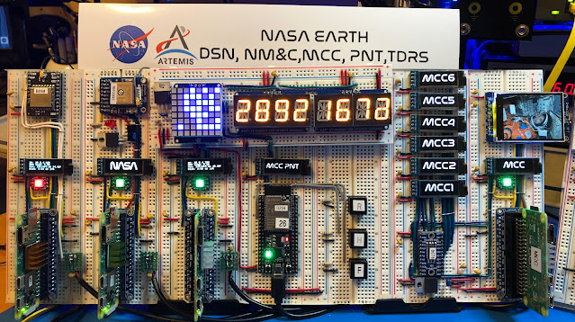
From the previous version I added two more nodes running on a Raspberry Pi Zero W 2, I expect in the future to add more as they become available, they are currently in short supply and are hard to procure.
There is a Raspberry Pi 3B+ with the sense hat also running Raspi OS and ION 4.1.1 that I use for testing code. And another two Raspberry Pi 3B+ running a complete different implementation of DTN called IBR-DTN from a University in Germany (more about it soon.)
I rearranged the nodes on the breadboards, and now the one implementing some of the functions of a Mission Control Center (MCC) has more displays, taking advantage of an eight channel I2C switch from Texas Instruments, the TCA9548A. With this switch it is possible to drive the seven 128x32 OLED displays that are associated with this node using a single I2C channel.
Also, on the MCC node I have now a 2” 320x240 IPS TFT LCD display, it uses the ST7789 TFT driver that can display full 18-bit color. The display module is connected to the SPI interface on the Raspberry Pi.
The idea is that at some moment those displays will show images transferred over DTN using Bundle Protocol, like pictures taking by a rover on the surface of the Moon (future node to be added using a Raspberry Pi with a camera), transmitted to a local relay node and from it through the Space Network to a ground station, and then through the Ground Network to a screen on JPL and/or MCC, all using Bundle Protocol.
On the previous version I was using independent power supplies for the Raspberry Pis, wiring was getting ugly and complicated. I replaced them all by single 5.1V 15A power supply, I had to put together some sort of power distribution adapter going to each of the breadboards where the Raspberry Pi are mounted.
If you have a good eye you will notice some LDO Voltage Regulators to step down from the 5V power supply to 3.3V required by some parts, particularly displays.
While on some nodes I can use the 3.3V generated by the Raspberry Pi Zero W2s, with the alphanumeric LED displays and too many OLED I was drawing too much power, then now some nodes have their own 3.3V LDO regulator.
I keep “the lab” running 24/7 monitoring power and some key signals, so far it has been reliable after I fixed the power distribution issues.
I took a Hack RF SDR I had in a box to check on the transmission signal levels of the LoRa modules, they are as expected centered on 915MHz, while they are low power modules, the signal can reach a hundred feet or more with a data rate of about 500bps, almost three times faster than Voyager 1, well the thing is 23+ Billion Kilometers away 😀😀😀.
On the software side I have a lot of work to do. Now I have all nodes running the same version of Raspi OS, they all have Circuit Python installed, NASA JPL ION 4.1.1 and all have Pyion 4.1 which is a Python programming interface for ION, so putting together a message to be sent over the DTN is simple as
import pyion
proxy = pyion.get_bp_proxy(1)
proxy.bp_attach()
with proxy.bp_open('ipn:82.1') as eid:
eid.bp_send('ipn:82.1', b'hello')
There is obviously and updated “Blinking Lights” video showing all the nodes running and some of the VNC screens from nodes, showing for example real time data from a GPS module, the message exchanges via LoRa, etc.
I started documenting the project, here is a diagram showing the current network topology configuration, this diagram does not represent the DTN communications topology.
Until the next inter planetary trip …
Cheers
Jorge


No comments:
Post a Comment