Monday, March 7, 2022

DTN-IPN New Node - Moon Rover

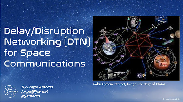
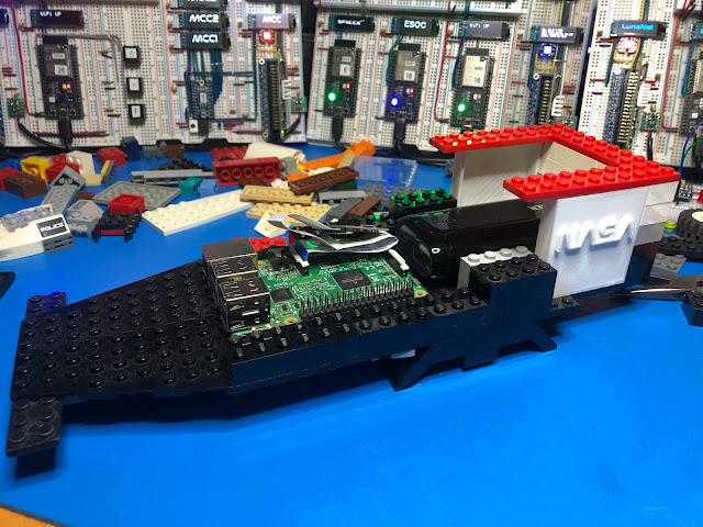
I was looking at my inventory of development boards and found that I had an extra Raspberry Pi 3B with the camera module. The camera is one of the early versions featuring the OV5647 image sensor.

I thought "I can use this setup to create another DTN node for the Lab prototype, what about a Moon Rover ?"

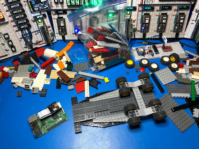
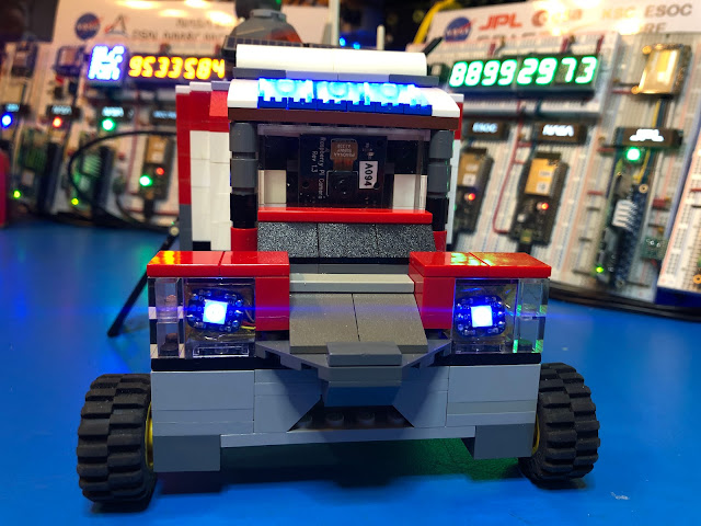
At first, I was thinking just to keep it in its original plastic case but then I realized that we have a bunch of Legos that our kids are not using anymore, so how about putting something together that looks like a lunar vehicle and can fit the Raspberry Pi, the camera and why not some lights and a battery.


I always had fun building stuff with Legos, I remember when I was a toddler in Argentina my Grandma use to take often to the “Rasti Club,” Rasti was another brand of building blocks available in Argentina at the time. I spent hours and hours building all sorts of gizmos.

Obviously, this model is just something I put together with what I had at hand, nothing that looks like a real rover or some of the Lunar vehicles under development like the JAXA/Toyota “Lunar Cruiser” for the Artemis mission.

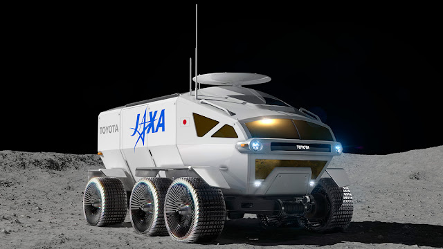
Picture Courtesy of JAXA

I was thinking about using one of the Lego design tools, but that was an overkill for this project. This could be a good idea for putting a contest or challenge together for students to design a Lego Lunar Rover that can accommodate the Raspberry and the camera. 

A Raspberry Pi Zero W 2 would also work and will take less space, but they are currently in short supply.

Let’s get started, with the parts I was able to “recycle” I started building sort of the chassis for the rover, taking in account of the size of the Raspberry Pi and enough height to fit the camera.

I 3D printed a pair of blocks with the NASA worm logo, the model file for it is available here.

I had to figure how to wire the Neopixels for which I used two channels on the Raspberry Pi, one on GPIO10, and the other one on GPIO21. Since I didn’t want to overload the onboard 3.3V power supply on the Raspberry Pi, I added an LDO regulator (Microchip TC1262) to get the 3.3V for the Neopixels directly from the 5V power supply.
I used wirewrap wire, and two small pieces of prototype pcb.


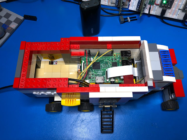
Quick test to confirm everything was working and putting the Raspberry Pi in place, connecting the camera flat cable and closing up.


Here is how the complete model looks from the left side
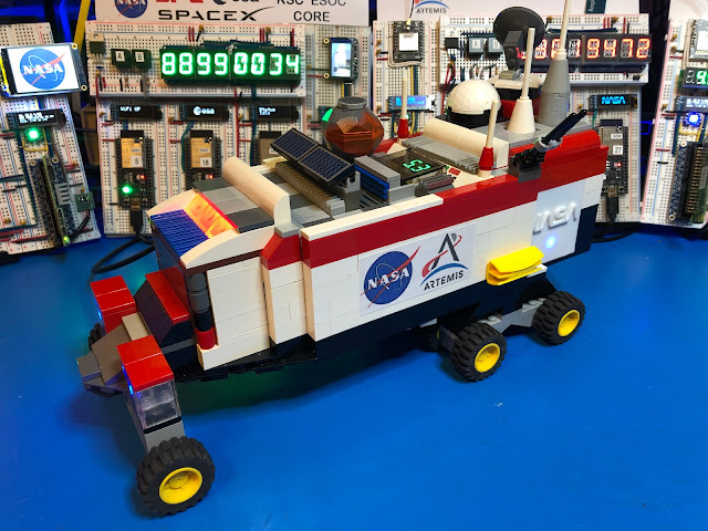

Right side look


Front with the camera module visible behind a transparent Lego block


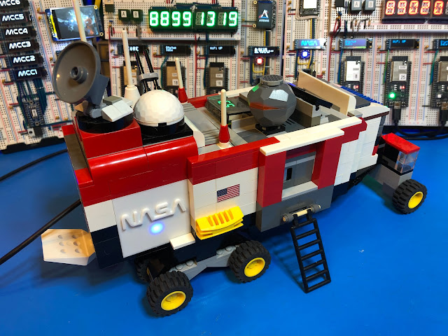
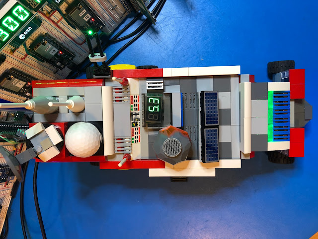
And the top, with a last-minute addition, a volt meter to measure input/battery voltage.


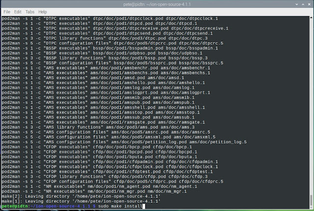
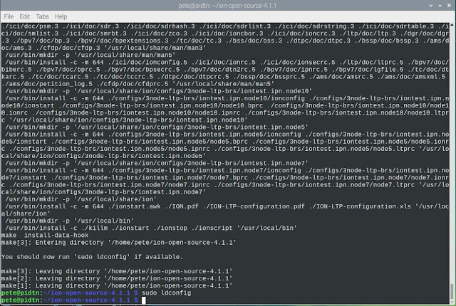
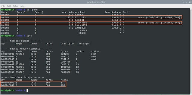
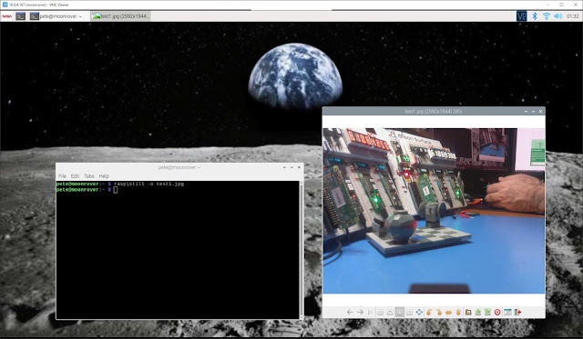
Connecting via VNC. Only thing that I was required to do to make it work was to enable the Camera interface with raspi-config, after that took the very first picture using raspistill.


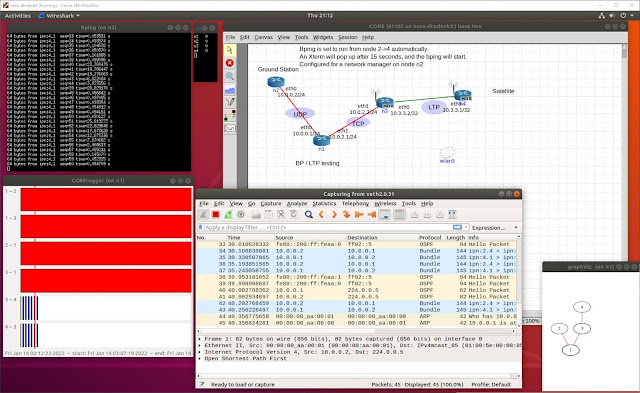
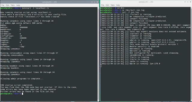
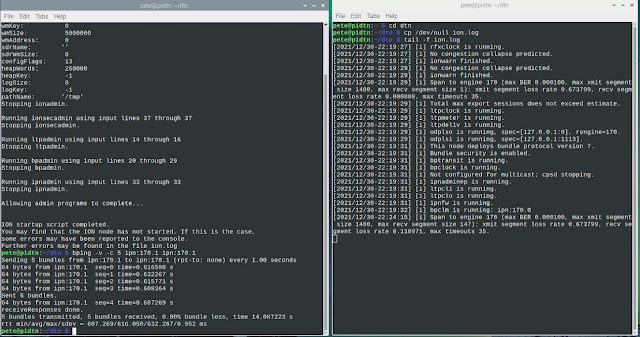
My plan is to write a script using Pyion to wait for a command to start taking pictures, store them in some spool directory and then wait for another command to start transferring them to a DTN relay with final destination, one of the nodes that have a TFT LCD display to show the images captured by the rover. All transfers using NASA’s JPL ION implementation of Bundle Protocols.

And of course, there is a video with a walk through and the blinking lights ðŸ˜Š

Once again if you are interested to learn more about this project, DTN and InterPlanetary Networking you can join the Facebook Group I created, and you can also join IPNSIG (ISOC InterPlanetary Networking Interest Group.)


Cheers
Jorge

Originally published on 2/8/2022

DTN-IPN R&D Lab Prototype Update

Happy New Year!!

Since my previous article on December 2021, I made some changes to the original design of the IPN-DTN Lab prototype that continues to be very much a work in progress project.


From the previous version I added two more nodes running on a Raspberry Pi Zero W 2, I expect in the future to add more as they become available, they are currently in short supply and are hard to procure.

There is a Raspberry Pi 3B+ with the sense hat also running Raspi OS and ION 4.1.1 that I use for testing code. And another two Raspberry Pi 3B+ running a complete different implementation of DTN called IBR-DTN from a University in Germany (more about it soon.)

I rearranged the nodes on the breadboards, and now the one implementing some of the functions of a Mission Control Center (MCC) has more displays, taking advantage of an eight channel I2C switch from Texas Instruments, the TCA9548A. With this switch it is possible to drive the seven 128x32 OLED displays that are associated with this node using a single I2C channel.

Also, on the MCC node I have now a 2” 320x240 IPS TFT LCD display, it uses the ST7789 TFT driver that can display full 18-bit color. The display module is connected to the SPI interface on the Raspberry Pi.


There is a new node implemented with a Raspberry Pi Zero W 2, I named it NASA-JPL, this node features also a 1.14” 240x135 TFT Color LCD mounted in portrait mode using the SPI interface of the Raspberry Pi.

The idea is that at some moment those displays will show images transferred over DTN using Bundle Protocol, like pictures taking by a rover on the surface of the Moon  (future node to be added using a Raspberry Pi with a camera), transmitted to a local relay node and from it through the Space Network to a ground station, and then through the Ground Network to a screen on JPL and/or MCC, all using Bundle Protocol.


On the previous version I was using independent power supplies for the Raspberry Pis, wiring was getting ugly and complicated. I replaced them all by single 5.1V 15A power supply, I had to put together some sort of power distribution adapter going to each of the breadboards where the Raspberry Pi are mounted.

If you have a good eye you will notice some LDO Voltage Regulators to step down from the 5V power supply to 3.3V required by some parts, particularly displays.

While on some nodes I can use the 3.3V generated by the Raspberry Pi Zero W2s, with the alphanumeric LED displays and too many OLED I was drawing too much power, then now some nodes have their own 3.3V LDO regulator.

I keep “the lab” running 24/7 monitoring power and some key signals, so far it has been reliable after I fixed the power distribution issues.

I took a Hack RF SDR I had in a box to check on the transmission signal levels of the LoRa modules, they are as expected centered on 915MHz, while they are low power modules, the signal can reach a hundred feet or more with a data rate of about 500bps, almost three times faster than Voyager 1, well the thing is 23+ Billion Kilometers away 😀😀😀.


On the software side I have a lot of work to do. Now I have all nodes running the same version of Raspi OS, they all have Circuit Python installed, NASA JPL ION 4.1.1 and all have Pyion 4.1 which is a Python programming interface for ION, so putting together a message to be sent over the DTN is simple as

import pyion 

proxy = pyion.get_bp_proxy(1)
proxy.bp_attach()

with proxy.bp_open('ipn:82.1') as eid:
    eid.bp_send('ipn:82.1', b'hello')


There is obviously and updated “Blinking Lights” video showing all the nodes running and some of the VNC screens from nodes, showing for example real time data from a GPS module, the message exchanges via LoRa, etc.


I started documenting the project, here is a diagram showing the current network topology configuration, this diagram does not represent the DTN communications topology.

I’m also drafting a paper and an introductory presentation about space communications evolution and DTN-IPN.


Now that I have a stable hardware and basic software platform running, I will be working in the actual DTN topology. This is very much a learning process for me as well, so I will be using a very interesting tool developed by the MITRE Corporation for an ION training course from NASA JPL.


I’m pretty sure that very soon I will be able to share some updates of what is happening at the InterPlanetary Networking Special Interest Group (IPNSIG), meanwhile if you want to learn more and join the conversation I have created a Facebook Group you can join.

Until the next inter planetary trip …

Cheers
Jorge

Originally published on 1/27/2022 here


Building NASA's JPL ION on a Raspberry Pi

 In my previous article you learned about the DTN-IPN R&D Lab project I’m working on, here I will start sharing how to build yourself a DTN node running NASA’s JPL Interplanetary Overlay Network (ION) protocol stack on a Raspberry Pi.

What do you need

  • Raspberry Pi single board computer, I’d recommend at least a version 3B or better 3B+, if you have a Raspberry Pi 4 it will also work. On my prototype lab project, I have several ION DTN nodes running on the new Raspberry Pi Zero W2 which is about five times faster than the Zero W. I did build ION on a Zero W and it worked just slower.

  • A microSD card of at least 16GB and decent speed with the Raspi OS image. I did use one of the latest stable versions for this project, the 2021-05-07-raspios-buster-armhf.img, no need for the full version since it will take more space on the SD card.
    You can download this version from the link above and prepare the micro SD card using Win32 Disk Imager on a Windows machine.


  • Obviously for the initial setup you will need a keyboard and a monitor, and a mouse if you will keep working directly on the Raspberry Pi. I normally after the initial setup and with a network connection I access it remotely via VNC or SSH, not necessarily but I usually change the default username “pi”.

Here are the steps to obtain and build the ION version 4.1.1 code on your Raspberry Pi:

1- After you have your board up and running make sure that you do to have the latest packages installed in your system
    sudo apt-get update
    sudo apt-get upgrade

2- It will be most probably already installed but just in case also do
    sudo apt-get install build-essential

3- And automake to build the scripts to compile the source code
    sudo apt-get install automake

4- Obtain the ION 4.1.1 source code tar ball from SOURCEFORGE
We will do this with 
wget on the Raspberry Pi


5 - Extract the ION source code distribution from the tar file.
You will notice that now you have a new directory named ion-open-source-4.1.1, change to that directory. If you are running on Raspi-OS Bullseye, you will have to run first the aclocal command, then run the configure script with./configure


This will check all the dependencies and configure the files to build the ION software, you may see some warnings but the script should end without errors.
 
6- You are now ready to build the code with make


You will see the compilation process step by step going through each directory of the ION source code, be patient, the Raspberry Pi can do the job, but it will take several minutes to complete the building process, it really depends on the speed of your Raspberry Pi and the micro SD card, but even with the slower Raspberry Zero W the code builds without problems.
 
7- After everything is built you should see a screen like this one, now you are ready to install the software, but pay attention for this step you must use sudo make install to perform the installation as the user root


8- You will see some warnings but don’t worry about them

Given that the ION software uses dynamic libraries we must perform one more step as root to run the ldconfig tool to create the necessary links and update the cache of shared libraries.


Now we are ready to run ION 4.1.1 on the Raspberry Pi, but first we need to create the configuration/startup file.

The ION implementation is modular, there are several processes that must be started but the configuration can reside in a single file.

Since for now we have a single DTN node, the first test will be a loopback test sending data bundles to the same node.

Let’s create a directory named dtn and edit a file named localhost.rc, we will use 170 as our node ID.


For the LTP (Licklider Transport Protocol) section instead of an IP address we will use for now 
localhost

For the Bundle Protocol we will declare LTP as the transport protocol, and define the input and output ducts (more about this soon.)

Your localhost.rc should look like this:

    ## begin ionadmin

    1 170 ''
    s
    # Contact plan definitions
    a contact +1 +86400 170 170 100000
    a range +1 +86400 170 170 1

    m production 1000000
    m consumption 1000000
    ## end ionadmin

    ## begin ltpadmin
    1 32
    a span 170 32 32 1400 10000 1 'udplso localhost:1113' 300
    s 'udplsi localhost:1113'

    ## end ltpadmin

    ## begin bpadmin
    1
    a scheme ipn 'ipnfw' 'ipnadminep'
    a endpoint ipn:170.0 q
    a endpoint ipn:170.1 q
    a endpoint ipn:170.2 q

    a protocol ltp 1400 100
    a induct ltp 170 ltpcli
    a outduct ltp 170 ltpclo
    s
    ## end bpadmin

    ## begin ipnadmin
    a plan 170 ltp/170
    ## end ipnadmin

    ## begin ionsecadmin
    1
    ## end ionsecadmin

In a future article I will go more into detail about the options for this file, meanwhile you can look at some additional documentation from Dr. Lara Suzuki.

Now it is time to start the protocol stack with ionstart. It will create a log file named by default ion.log in the directory from where we launch ionstart. Since I want to see the log in action, I will create an empty ion.log file and run tail -f ion.log, and in another terminal window launch ION using ionstart with the -I option to include to config/startup file.

Here you can see both terminals side by side


Like for the Internet Protocol (IP) we have a similar tool to ping, for Bundle Protocol (BP) it is called bping ðŸ˜Š

When using bping we need to follow the naming scheme for DTN, telling the originating and destination nodes and endpoints, which is something like scheme:nodeID.endpoint. I will use my node ID in both cases ipn:170.1, the -v option to make it verbose and -c 5 to send just five bpings, here you go


Yeah you just did your first test running the ION DTN Bundle Protocol stack !!

There are some tools that can help check the status of your DTN stack like ss to see the  active sockets, and ipcs for information on IPC (Inter Process Communication) facilities like  the mutex semaphores created by the Bundle Protocol stack.


You are one step closer to be able to communicate with space objects and other ION nodes.

Like ionstart, there is a ionstop command to stop the ION protocol stack and kill all the associated processes.


In a coming article I will show how to create a Virtual Machine running Ubuntu Linux and build ION on it, then we will have two nodes to start exchanging messages using the Bundle Protocol.

Until then here is some reading material from Scott Burleigh the main author of the ION implementation of the DTN Bundle Protocol.

At the IPNSIG (InterPlanetary Networking Special Interest Group) soon to be Internet’sSociety Interplanetary Chapter, there are plans to have a test network where everybody will be able to participate and help testing DTN at a larger scale.

If you have questions please feel free to leave your comments below. As always, constructive feedback is welcomed.

Stay tuned for future updates, and if you are interested to exchange ideas and learn more you are welcome join the Inter Planetary Facebook Group and join IPNSG !!

Happy Networking and Happy New Year !!

Cheers
J
orge

Originally Published on 12/31/2021 here